1. Polarization Issue:
The problem might be polarization. Our Tx is circular polarization and Rx is linear polarization, it is
not an ideal match in nature. As a result, we decide to move Tx back to Lab and setup IC-1000 to see what's wrong with our Tx antenna.
Chart1 2.5M parallel loop antenna
Red curve is Max. Envelop
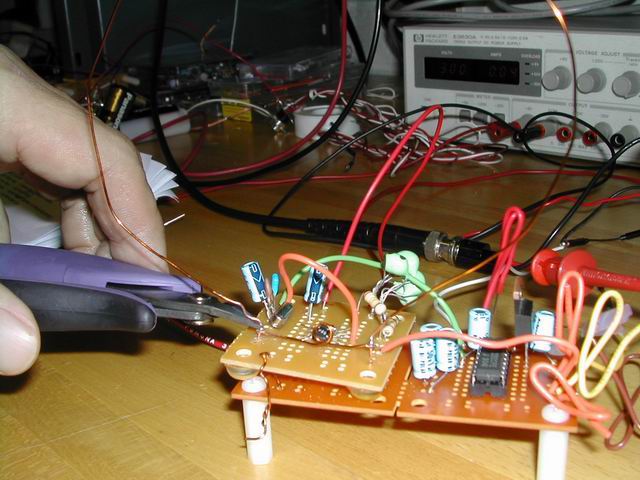
2. Cut the loop:
When we are about to cut the wire, the received power boosts significantly! That is a surprises to us. We analyze that phenomenon and
find out the cause. A clipper conducting the antenna changes the polarization from circular to somewhat linear polarization. It is a like
linear polarization because of the two handles of clipper, and if is in upright position, it matched the receiver polarization ( vertical
linear polarization). To prove this, we record the chart.
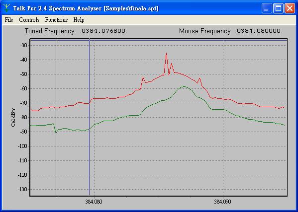
Chrat2 2.5M Clipper phenomenon
The Red curve depict the max received power with a clipper and green curve is transient curve without clipper. Comparing with Chart1,
The max power is boosted by 20 dBm.
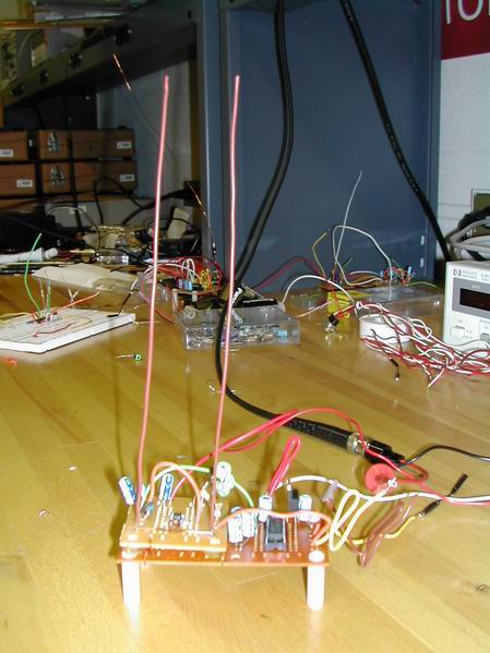
3. Change Loop antenna to Dipole antenna.
The standard dipole should be like this :
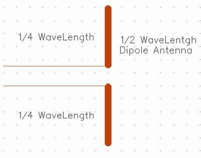
Due to the original design of Tx IC , there is a internal capacitor that shouldn't exist in Dipole antenna configuration. The way to cancel out the capacitance is like the way we used in loop antenna; we add a additional inductance to resonate out the capacitor at Tx frequency.
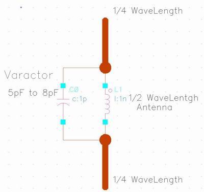
The inductor should be 21.5nH to 35.5nH and we could use the small loop(27nH) we made for loop antenna. Now we have a dipole antenna. We make a little experiment on " How does the antenna position affect the received power ? " by placing different antenna positions.
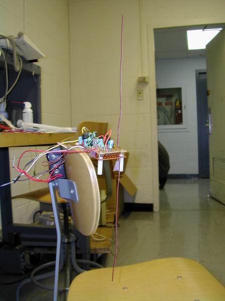
4. Antenna Test
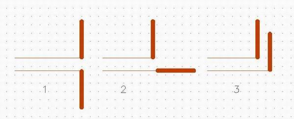
1. 1 rod points up, 1 points down
The test result conforms the theory, 1 > 2 > 3 in received power if receiver is vertical polarization.
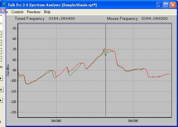
Chart3 2.5M Antenna test: Configuration 1 and 3
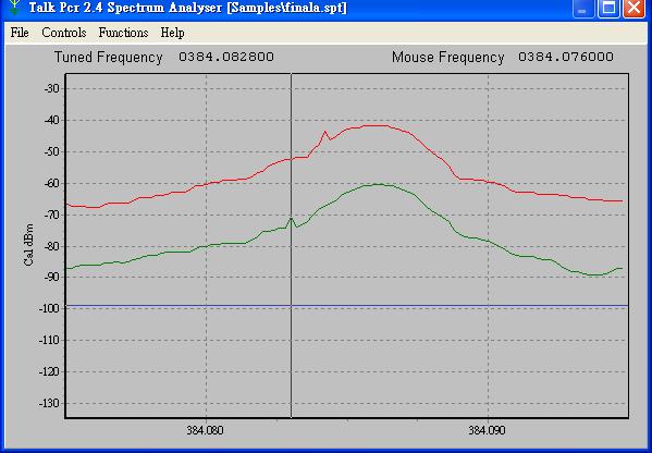
Red curve depicts the max envelop of configuration1 , green curve is transient of configuration 3.
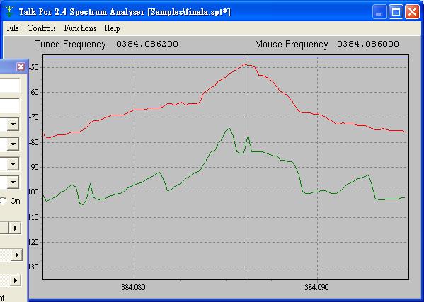
Chart4 2.5M Antenna test: Configuration 1 and 2
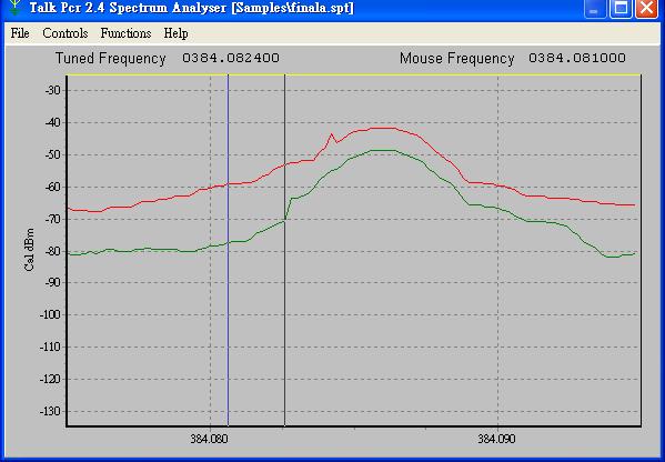
Red curve depicts the max envelop of configuration1 , green curve is transient of configuration 2.
Configuration 1 is about 42 dB, configuration 2 is about 50 dB, configuration is about -60dB. The difference is about 10 dB to each other. In Configuration 3 energy seems to cancel each other and is be avoided. Configuration 2 could be used when the Rx polarization is unknown. To test the efficiency of the small loop ( additional inductor), we take it off and measure the received power.
Chart5 2.5M Without small loop (additional inductor) , Configuration
1 and
3
Red curve depicts the max envelop of configuration1 , green curve is transient of configuration 3.
Comparing with Chart3, the max envelop drops 10dB and the envelop is not as smooth as chart 4 or 3. There exists spikes in Chart1 and Chart5, and we think it might be a syndrome of unmatched antenna. New antenna successfully boosts Received power by 20 to 25dB than old loop antenna. To see the improvement in data transmission, we have to perform 2 PCs data link test.