
1. 1/2 λ Loop antenna with a parallel inductor
The Rx IC ( Micr011) is designed to drive a 1/4 λ antenna. and Tx IC is designed specifically to drive a loop antenna.
For Rx, 1/4 λ antenna is a just 19.5 cm wire. For Tx, loop antenna design is more complicate.
In loop antenna design, the loop better to be λ or 1/2 λ and it should resonate at ftx with a internal capacitor ( Varactor). The
Inductance should be L=1/4(π^2) (ftx^2) C . After the calculation, L should between 21.5 nH to 34.4 nH.
A 1/2 λ Loop antenna has a diameter of 12.43cm . The inductance of the total Loop is calculated as 390.4nH

N =1 R= 6.215 cm a=0.045cm ur=1 for copper wire.
( N =number of turns; R=radius of circle; a=wire radius; ur=relative permeability of medium)
390.4nH antenna is apparently beyond the upper bond allowable inductance! To make a power-matched antenna, we have to do
some modification. What we do is to design a small inductor and make the paralleled inductance down to 25nH .
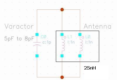
390.4nH // 27 nH = 25.25 nH. A 27 nH inductor will be: 2 loops , R = 0.285 cm, a=0.045 cm , ur =1.
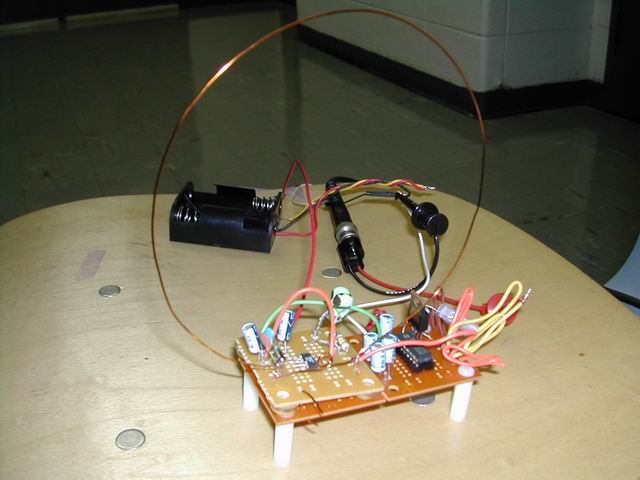
We make it 2 loops because it is more robust than single loop. The final antennal looks like this.
2. Observation: with loop and without loop
To make sure whether it works or now, we use a "all-band" receiver IC-1000 to measure the received power and use
Function Generator as signal source. Testing environment is corridor out side the lab and range is 40M. We do experiment with and without the
27 nH inductor.
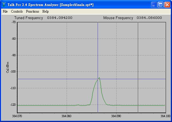
The result is pretty much like what we expect. Without a parallel loop, the received power drops significantly. The signal drops about 10 dB.
2 With parallel loop, 40 M
Without parallel loop , 40 M
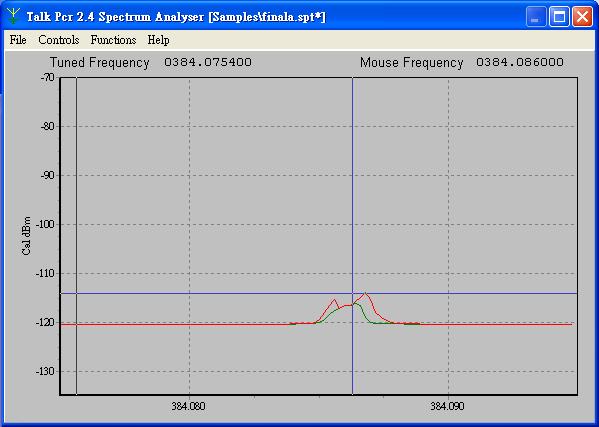
Red curve is max. envelop
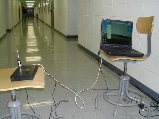
2 PC Test
Although the experiment above shows the additional small loop does work, we notice that the received power is too small to be picked up by Rx. The 2 PC test proofs our worry. The Range vs Error rate test result is so bad. Beyond 6 meters , Error rate is 100 %. This is totally unacceptable