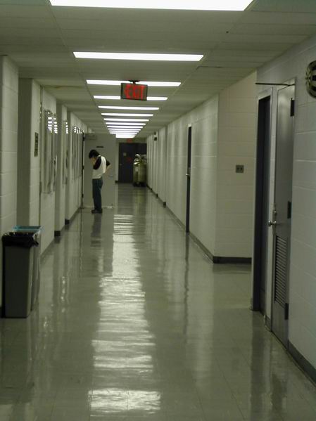
The Test field is the corridor out side the lab as before, and the max distance (end to end) is 55M. A metal door is open at 35M.
We decide using 1st. antenna configuration for its best performance.
1. We tested Vertical and Horizontal Polarization ( the same Polarization in Tx, Rx )
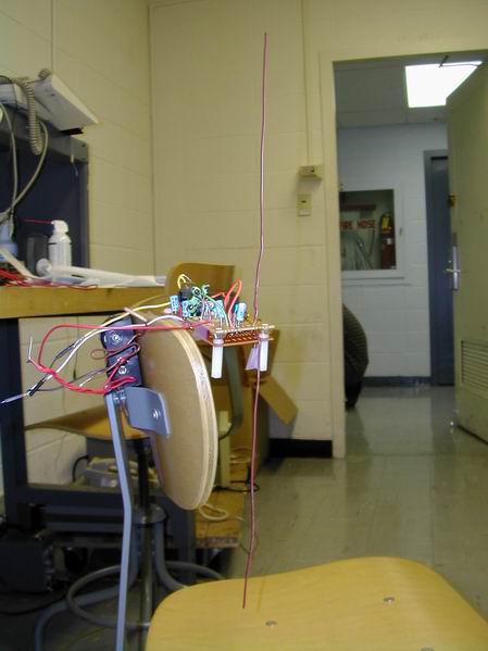
2. Tx, Rx are fixed on Lab chair.
3. In A certain range, we count error rate 10 times in both 1200bps and 2400bps.
4. Rx and Tx are in line of sight all the time.
5. Rx and Tx are powered by battery.
6. 100 words are transmitted in each time.
2. Test Result
Range ≦30M
| Vertical | |||||||||||
| Test Noumber | 1 | 2 | 3 | 4 | 5 | 6 | 7 | 8 | 9 | 10 | Avg |
| 1200bps Error Rate % | 0 | 0 | 0 | 0 | 0 | 0 | 0 | 0 | 0 | 0 | 0 |
| 2400bps Error Rate % | 0 | 0 | 0 | 0 | 0 | 0 | 0 | 0 | 0 | 0 | 0 |
| Horizontal | |||||||||||
| Test Noumber | 1 | 2 | 3 | 4 | 5 | 6 | 7 | 8 | 9 | 10 | Avg. |
| 1200bps Error Rate % | 0 | 0 | 0 | 0 | 0 | 0 | 0 | 0 | 0 | 0 | 0 |
| 2400bps Error Rate % | 0 | 0 | 0 | 0 | 0 | 0 | 0 | 0 | 0 | 0 | 0 |
Range = 35M
| Vertical | |||||||||||
| Test Noumber | 1 | 2 | 3 | 4 | 5 | 6 | 7 | 8 | 9 | 10 | Avg. |
| 1200bps Error Rate % | 53 | 47 | 61 | 59 | 87 | 43 | 71 | 42 | 63 | 55 | 58.1 |
| 2400bps Error Rate % | 62 | 47 | 31 | 85 | 43 | 87 | 49 | 87 | 41 | 64 | 59.6 |
| Horizontal | |||||||||||
| Test Noumber | 1 | 2 | 3 | 4 | 5 | 6 | 7 | 8 | 9 | 10 | Avg. |
| 1200bps Error Rate % | 4 | 4 | 2 | 3 | 5 | 4 | 7 | 3 | 3 | 2 | 3.7 |
| 2400bps Error Rate % | 0 | 0 | 0 | 0 | 0 | 0 | 0 | 0 | 0 | 0 | 0 |
Range = 40 M
| Vertical | |||||||||||
| Test Noumber | 1 | 2 | 3 | 4 | 5 | 6 | 7 | 8 | 9 | 10 | Avg. |
| 1200bps Error Rate % | 100 | 100 | 100 | 100 | 100 | 100 | 100 | 100 | 100 | 100 | 100 |
| 2400bps Error Rate % | 100 | 100 | 100 | 100 | 100 | 100 | 100 | 100 | 100 | 100 | 100 |
| Horizontal | |||||||||||
| Test Noumber | 1 | 2 | 3 | 4 | 5 | 6 | 7 | 8 | 9 | 10 | Avg |
| 1200bps Error Rate % | 0 | 1 | 0 | 0 | 0 | 1 | 0 | 0 | 0 | 0 | 0.2 |
| 2400bps Error Rate % | 0 | 0 | 0 | 0 | 0 | 0 | 0 | 0 | 0 | 0 | 0 |
Range = 45 M ( Vertical Polarization Fails to transmit after 40M)
| Horizontal | |||||||||||
| Test Noumber | 1 | 2 | 3 | 4 | 5 | 6 | 7 | 8 | 9 | 10 | Avg. |
| 1200bps Error Rate % | 7 | 1 | 2 | 4 | 5 | 0 | 1 | 7 | 6 | 0 | 3.3 |
| 2400bps Error Rate % | 0 | 0 | 0 | 0 | 0 | 0 | 0 | 0 | 0 | 0 | 0 |
Range = 50 M
| Horizontal | |||||||||||
| Test Noumber | 1 | 2 | 3 | 4 | 5 | 6 | 7 | 8 | 9 | 10 | Avg. |
| 1200bps Error Rate % | 2 | 1 | 1 | 2 | 2 | 3 | 2 | 3 | 4 | 2 | 2.2 |
| 2400bps Error Rate % | 1 | 0 | 0 | 0 | 0 | 0 | 0 | 1 | 0 | 0 | 0.2 |
Range = 55M
| Horizontal | |||||||||||
| Test Noumber | 1 | 2 | 3 | 4 | 5 | 6 | 7 | 8 | 9 | 10 | Avg. |
| 1200bps Error Rate % | 5 | 4 | 3 | 8 | 7 | 3 | 4 | 8 | 4 | 4 | 5.0 |
| 2400bps Error Rate % | 0 | 0 | 1 | 0 | 0 | 0 | 0 | 0 | 0 | 0 | 0.1 |
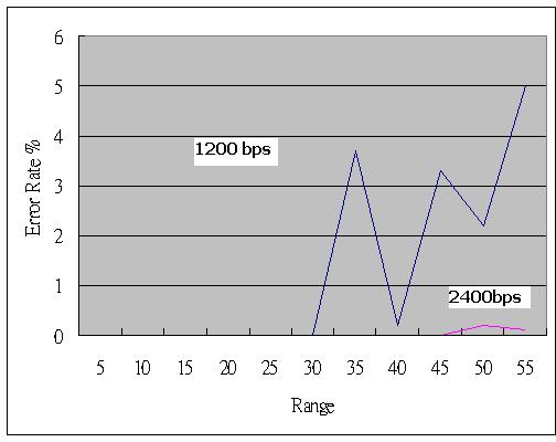
Horizontal Polarization
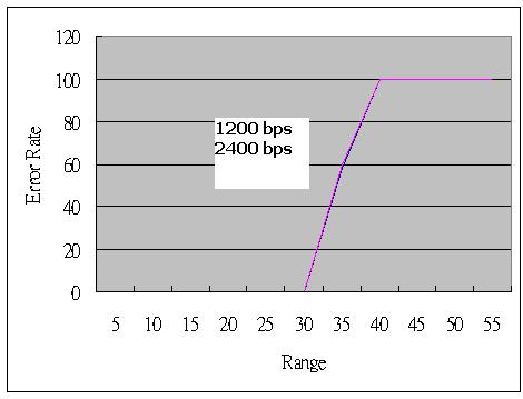
Vertical Polarization
3. IC-1000 Received Power, 55 M
Chart1. Horizontal Polarization

Red curve is Max envelop
Chart2. Vertical polarization
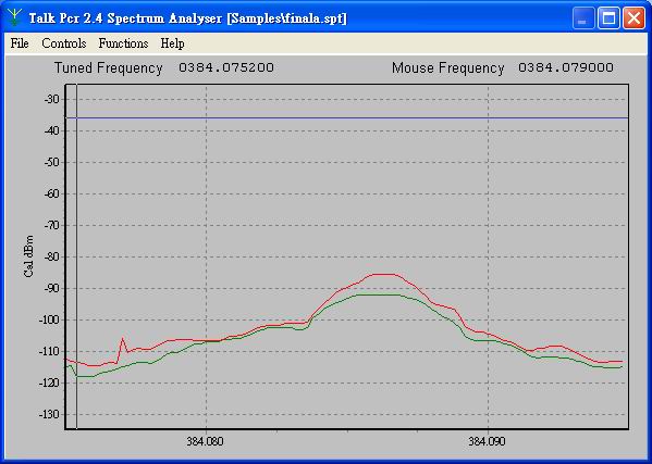
Red curve is Max envelop
Chart3. Tx : Horizontal Rx: Vertical

Green Curve only
4. Analysis
1. As you can see, Vertical polarization fails to transmit after 35 M but Horizontal Polarization still works good. The reason should be the environment differences. In Vertical polarization, EM wave is reflected and deflect by more complicated surroundings such as door, , uneven sidewall, and corridor branches. On the other hand, EM wave in Horizontal polarization is mostly reflected by ground and ceiling, which is a simpler environment. Complicated surrounding will bring multi-path effect and results in inter-symbol noise which is really detrimental to digital signal integrity.
2. When we set Tx in Horizontal and Rx in Vertical (Chart3), the 2400 bps error rate is about 5% to 10 %. What should be noted is that although Rx power received in Chart3 (Horizontal to Vertical , -98dB) is less than Chart2 ( Vertical to Vertical, -90dB), its error rate is much less than chart2 (fail to transmit). This implies received power is not the only factor of error rate. Issues such as inter-symbol mentioned above should be taken into consideration too.
3. Another observation is : Error rate of 1200bps is greater than 2400bps. A possible is the bandwidth (baseband) set in Rx is good for 2400 bps, but too large for 1200 bps. Larger bandwidth might bring noise which might interferes signal integrity. Further experiment should be done to prove this.
5. Power Consumption:
|
Mode |
Current |
Voltage | Power |
| Rx (StandBy) | 13.434 mA | 6V | 80.604 mW |
| Rx | 13.278 mA | 6V | 79.668 mW |
| Tx (StandBy) | 12 mA | 3V | 36 mW(@2400 bps) |
| Tx | 36 mA | 3V | 108 mW(@2400 bps) |
-