1. Interface
If you connect PC(Rs232) with Tx / Rx directly, you will find it doesn't work because they say different language.
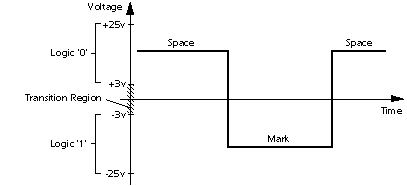
Voltage definition in Rs232 and CMOS (Tx / Rx )
In our Tx / Rx , "0" is defined as "0V" and "1" is "5V". In Rs232, logic signals are not defined the same way.
Signal is considered logic "1" when voltage is -3V to -25V. Logic "0" is defined if voltage is is "3v to +25V"
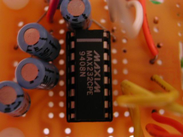
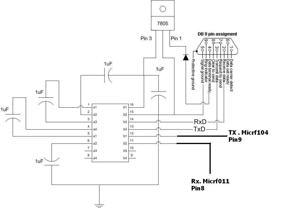
Interface chip : Maxim max232cpe
This chip is designed to convert signals between Rs232 and CMOS. Though it has two channels, we only need one of them to do
the conversion. The power regulator 7805 is used to steal power from Rs232. (See Schematic 3)
2. Power Integration
Although our Tx / Rx pass the preliminary test, it is not practical because it needs power supply. Next step is to use batter instead of power supply and make it really "portable".
Receiver
Micrf011 need 5 V , so does max232. We can have 6 V by making 4 X 1.5 V batteries. 6 V is still acceptable for chips.
Transmitter
Micrf011 can work from 1.8V to 4 V, so we make 3 V with 2 batteries in series. It will transmit max. power (2.5dbm) when Pin11(Power Control) is above 0.45V. To make sure it will transmit max power, we make a resistance divider to bias Pin11. Resistor are 390k and 100k, and pin11 is bias at 0.6 V when battery is full. We try to keep resistor high to save power.
Max232 needs 5 V and seems not possible by 3 V battery. To solve this problem, a power regulator is used to steal power from PC. It works, but the power is only enough for 1 Max232, which means max232 in Rx still have to rely on battery.
3. 1 PC Test, Noise problem
NOISE Observation
After solving interface problem and integrating power on board, we can perform real data transmission test. We start from one PC.
The result is unacceptable. Rx does pick up data when Tx is sending them, however when Tx is not sending data, Rx picks up noise. The noises are converted by Max232 and finally is shown as random characters on screen.
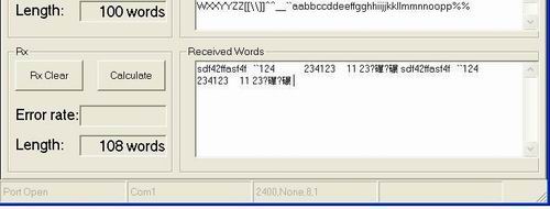
We checked documents in Micrel website and found they have the same problem reported. " As is common with all super-heterodyne AM receivers, the output will contain noise when there is no RF carrier present. The operation of AGC and the demodulator in the Micrf001 converts very low level noise into a corresponding logic level noise " There are two ways to solve the problem: analog squelch and digital squelch. We choose analog squelch because we didn't have time to wait for another micro controller to perform digital squelch.
As to the "Application Note 28", the voltage on Pin7 is the threshold voltage to determining noise or Signal. Adding a small offset on this pin could raise the threshold voltage so noise will be "filtered" out and no logic-level noise will be produced. We performed a series of testing and find the best voltage on Pin7 is from 1.594v to 1.645v.
The Good news is: Analog squelch works , but the bad news is: The tolerable voltage range is so small (0.05v), how can we produce this voltage without using power supply ? It seems we hit a stump.
Solution:
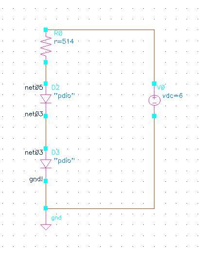
We came up with a solution the next day. Making 2 diodes and 1 resistor in series, voltage across two diodes (net05) will will be around 1.5 V.
If choose the resistance right, such that I x R = 6- 4.4 V, then (net05) will be 1.6V. It requires some try and error. When both diode are conducting, a voltage variation will also incur current variation with Gain (I/V) > 1 which brings the additional bigger voltage drop across R. It seems like a a CE amplifier and the output is voltage across battery.
Battery is like a capacitor providing constant voltage before it dies. It's voltage decays when it runs out energy, which also brings down the voltage on net05 but only by 1/G battery voltage drop. Voltage variation in net05 is attenuated.
If we choose a proper R, and Diode variation of net05 can be limited in the acceptable range (1.594V ~ 1.643V) when battery is among 6.3 V (full) and 5.5 V (dead). To make sure it works along the voltage life, a power supply is used to "simulate" Battery voltage.
We choose R = 514 and 2 T1711 diodes.
|
V across diodes |
Vdc |
|
1.6425 |
6.37 |
|
1.6320 |
6.20 |
|
1.6261 |
6.07 |
|
1.5946 |
5.49 |
Disadvantages:
1. It burns additional Power that is about 42mW. ( 37 mW by R, 5 mW by diodes, SPICE simulation)
2. Voltage across diodes is "sensitive" to R. It will be a problem in mass production.
4. 2 PC Test
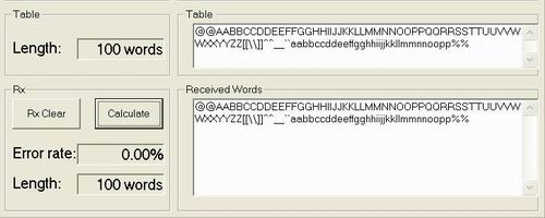
The Result is satisfactory. In short range test ( Tx/Rx apart by 1.5 m), error rate in "0" in both 2400 bps and 1200 bps transmission.
However, when range goes up to 3 meters , Error rate rises significantly to 50 % . They might be attributed to antenna design, so the nxst step is to design a better antenna.