1. IC selection
To comply our requirement, we survey the several Tx / Rx IC and find Micrel has the IC might work for us.
We choose Micrel Micrf104 and Micrf011 as our Transmitter and Receiver IC.
Figures of Micrf104 (Tx):
Complete ASK/OOK transmitter on Chip
Frequency 300 MHz to 470 MHz
Data rates to 20kbps
Automatic antenna tuning.
Variable Supply voltage (1.8V to 4 V)
Max output power 2.5 dBm
Figures of Micrf011 (Rx):
Complete ASK/OOK receiver on Chip
Frequency 300 to 440 MHz
Data rates to 2.5kbps (SWP),10kbps (Fixed)
Automatic antenna tuning.
Low power consumption
Receiver sensitivity is -103 dbm
2. Frequency and Range calculation
The Tx frequency is set around 400 MHz. (Calculation based on Micrf104 and Micrf011)
Pr( received power), Pt( transmitted power ),PL (power loss), Gt , Gr Tx/Rx antenna gain.
Pr = Pt + Gt + Gr - 20log( 4π / λ) ... free space
Using the power budget for cellular radio
PL = PL (do) + 10n log (d/do) ...long distance model.
do = free space reference distance, set to 1 m
PL(1m) = 24.4829 dB
n= 2.7 ~ 3.5 for Urban area cellular radio
Spec. of Micrf104 and Micrf011
Pr min = -103 dBm , Pt max. = 2.5 dBm PL max ≈ 100 dB
100 = 24.48 + 27log(d/1)
d= 625 m when n=2.7
d=143 m when n=3.5
3. Crystal and Rx mode selection.
Transmitter ( Micrf104 ) ftx = 32 x fref
Crystal oscillator is chosen because it provide accurate and stable oscillation. We find 12MHz crystal, so ftx = 32 x 12 =384MHz
Receiver ( Micrf011)
There are two operating modes in receiver, Fix mode and Sweep mode.
Fix mode
In Fixed mode, Rx frequency is exactly the same as Tx frequency. It provide higher Rx speed (10kps)
flo (Internal Local Oscillator)= ftx ± 1.064 * ( ftx / 390)
frf = flo / 64.5
for ftx = 384 MHz , frf = 5.96973 MHz or or 5.93726 MHz
Unfortunately, we can't find oscillators in either the frequency.
Sweep mode
In sweep mode, the internal local oscillator is swept across a band of frequency in the vicinity of a certain frequency (frx).
The advantage is that we don't have to set Tx / Rx at exactly the same frequency. The disadvantages are :
the upper limit on data rate is approximately 2.5kbps.
range penalty occurs If there exists a competing signal of sufficient strength in this small frequency band. 2.5 kbps is enough for us to report location data.
The sweeping range is ± 0.5% of frx. The crystal oscillator we can find best is 5.9904 MHz (frf), which can provide 384.88MHz in frx (frx = 64.5 x frf). The available receiving range is frx ± 0.5% = 386.80 MHz to 382.95MHz that covers our Tx frequency, 384 MHz.
|
Tx Frequency |
384 MHz |
|
Rx Frequency |
382.95MHz ~ 386.80MHz |
4. Build Tx / Rx module
If you try to buy less than 10 chips from Web, shipping fee is usually more expensive than the price of IC's. What you can do is to ask samples from dealers. Most of them are willing to provide some chips <10 to students.
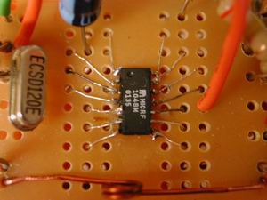
Basic Transmitter Module
Micrf104 is in SOIC package, which is smaller than DIP package and can not be plugged on breadboard. As a result, first we glue it on a small pc board, when it is fully dried, connect metal fine wires and it's pin by soldering. It must be done very carefully because the soldering point of wire and pin is small and is very easy to short another pins. Avoid touching pins directly by soldering tip, it might burn down the chip.
This chip could
be divided in to voltage convertion part and RF transmission part. The fist
part is to convert input voltage (1.8 ~ 4 V) to 5 V,
which will be used in RF transmission part. The value of surrounding capacitor and inductors are listed in the manual.
The suggested inductor is 22uH, but the smallest one we can find is 100 uH, so we make 4 100uH in parallel and it becomes 25u H.
To work in Sweep mode, pin12 should be high.
Pin11 is to control Tx power. To have max. power, Pin11 must > 0.45 V. A another power supply is need.
A temporary Loop antenna could be done by a wire connecting ANTM(PIN7) and ANTP(PIN8)
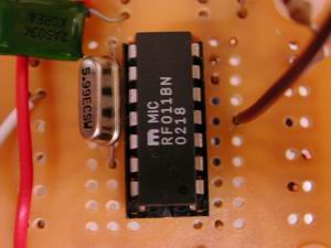
Basic Receiver Module
Comparing to transmitter, receiver is easier to be done. The Rx IC ( Micrf011) come in DIP package. To prevent burning down it when soldering it, we solder a socket on PCB first and plug in the IC when all the components are in position.
Optima demodulator bandwidth is 0.65/Minimum Pulse Width = 1.560k for 2400kbps and 0.78k for 1200kbps.
Antenna is a 1/4 λ Dipole Antenna. We use a piece of wire with length 19.5 cm.
Pin 14 must be enable to enter Sweep mode.
5. First Test
Before running channel test, we do the following check.
Transmitter :
Is Pin3 (5V) 5 V ?
Is Pin14 (EN), Pin 6(RFSTBY) enable ?
Is Pin10 (VDDRF) 5 V?
Is crystal oscillator working ? (Use oscilloscope )
Is Pin11(Power control) at the voltage you want ?
Receiver:
Is Pin14(SWEN) enable ?
Is crystal oscillator working ?(Use oscilloscope)
After the checks, we can hook up Function Generator (FG) to Tx and Oscilloscope to Rx. Make sure the FG signal comply with the
input requirement of Tx IC . ( 0 ~ 5 V )
It works ! the Oscilloscope shows the correct wave form.
The next step is to develop a program and use PC to run a real "data" test...