Frequently Asked
Questions
Q: What is the equation for the parasitic resistor in the inductor model?
A: In reality, the value of the parasitic resistor depends only on inductor value and layout structure. However, when we model the inductor, we define a Q value for a certain narrowband frequency range. The value of the Q depends on the value of inductor, the value of resistor and the frequency. In the given model, the Q of the inductor is defined as 7 for the 2.4 GHz ISM band. So, you can derive the value of the resistor for Q of 7 and frequency of 2.45 GHz. If you don’t know the equation for Q of an inductor, please check some textbooks (T. Lee: "The design of CMOS Radio-Frequency Integrated Circuits” ) or try to derive it by yourself.
Q: What is the load of LNA?
A: Since it is a quadrature receiver, the outputs of the LNA are connected to two mixers. You may check some 2.4 GHz receiver publications and have an idea about the transistor sizes of the mixer seen by the LNA outputs. Then you may have an approximate model for the load of LNA by putting some dummy devices at the outputs with appropriate sizes at the specific operating point. You may also model the load as a capacitor and find the approximate value of it by calculating the input capacitance of the transistors. If you can’t find any information about the transistor sizes of a 2.4 GHz ISM band mixer, you may use a replica of the input transistor of your LNA as the load of your LNA.
Q: What is the input interface of the LNA?
A: The S-paramater models for RF BALUN and RF switch that have been used before LNA will be given later at the last assignment for the simulations of the whole receiver. For the LNA design, please use the following input interface in your simulations.
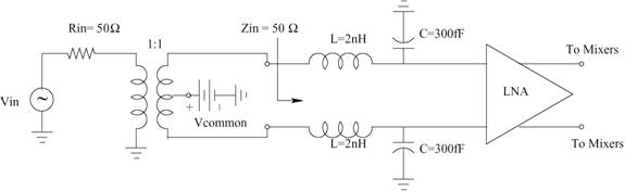
The BALUN shown in the diagram is
an ideal 1:1 BALUN.
Q: How can I measure the NF of the LNA?
A: Please check the definition and calculation of NF at Razavi’s RF Microelectronics book (pp 39-43). After you have done a noise simulation for your LNA, you may easily calculate the NF of your LNA by using the formula given in the book.
Q: How can I measure the IIP3 of the LNA?
A: Please check the definition and calculation of IIP3 at Razavi’s RF Microelectronics book (pp 17-22). You have to make a couple of two tone test for this measurement with two inband signals, such as 2.410 GHz and 2.414 GHz. Then you may calculate the value of IIP3 as it is shown in Razavi’s book.
Q: What does LO = 300 mVpp and Power(RFIN)=-30dBm mean?
A: It is to measure the LO feedthrough to RFIN and IFOUT terminals under the assumption that there is 1% mismatch between the transistors of differential pairs, and under the condition when the LO voltage is 300mVpp and the RF input power is -30dBm.
Q: How can I run PSS and PNOISE analysis in spectreRF?
A: Please check the spectreRF tutorial in your ‘cdsdoc’. The tutorial explains everything that you may need when you are using the spectreRF simulator. It also gives you examples of how to simulate mixers, LNAs and oscillators with specrteRF. I am putting up a link to the tutorial for who do not have access to the ‘cdsdoc’.