Continuous-Time Digital Signal Processing


Motivation1

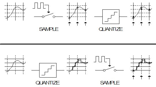
     Conventional digital signal processing (DSP) samples the input, then quantizes the amplitude value at the discrete sampling time into a finite-bit representation. There are two processes here: amplitude quantization and time discretization. The former is the essence of DSP, using a finite number of 'bits' to represent the analog input signal. The latter is an effect of using a synchronous (clocked) system, that updates internal states at regular intervals. The effect of amplitude quantization is, for an example case of a sinusoidal input, to introduce harmonic distortion (as demonstrated below in Fig. 3). The effect of sampling is aliasing, or repetitive folding of the signal spectra. What is critical to note is that even though conventional DSP samples and then quantizes, if you reverse the order of operations (quantize in a continuous-time (CT) fashion and then sample), the result is the same (pause to consider this! If still unclear, see Fig 4. at the bottom of this page). In Fig. 1 the spectra of a single sinusoid is shown: quantized and then sampled (Fig. 2 shows time-domain waveforms of these signals, using 3 bits of amplitude quantization). This order of operations makes it clear that the sampling operation introduces a significant amount of distortion into lower frequencies, by aliasing down the distortion introduced by the amplitude quantization. As a highlighting example, for a system of interest that is of a low-pass nature, consider the amount of distortion in any given bandwidth in the middle versus right-most plots of Fig. 1. The plot on the right has the same amount of harmonic distortion as the center plot, plus additional aliased harmonic distortion. This means that for any bandwidth, the center plot is guaranteed to have a higher signal-to-distortion ratio (SDR) than the plot on the right. Note that the example shown in Fig. 1 is assuming no blockers, noise, or any other form of corruption. If there were, a normal system would use an anti-aliasing filter so that after sampling out-of-band blockers would not alias down into the band of interest, but the aliasing occurs (in Fig. 1) only after the quantization, so if processing is performed on solely the post-quantization but pre-sampling signal, out-of-band blockers will not alias down and corrupt the signal, a significant advantage. Taking advantage of this (guaranteed higher SDR by not aliasing down the distortion caused by quantization, and not aliasing out-of-band blockers) is the motivation to move to continuous-time DSP.

Fig. 1 Progression of spectra of input sinusoid: quantize then sample.


Fig. 2 View of an input sinusoid (red) and its 3-bit CT quantized output (blue). The green curve shows the error signal, which is clearly related to the input.


CT-DSP1

     CT DSP uses digital signal processing structures (digital filters, digital adders, etc.) but without ever sampling the input signal. The system 'tracks' the input at all times and thus must have sufficient speed to keep up with the input and its fastest rate-of-change. The benefit to this is that there is no aliasing of out-of-band distortion components (arising from amplitude quantization) or any other out-of-band content. Fig. 3 compares the spectra at the output of two digital low-pass filters (LPF), one a CT DSP and the other a conventional DSP with a 44.1 kHz sampling rate. It is clear that the CT DSP has much less in-band distortion, and thus a higher SDR.
     To get an intuitive feel for CT DSP, note that the only difference between CT DSP and conventional DSP is that in CT DSP there is no uncertainty about the time an event happens, while in conventional DSP the signal may change from sampling instant to sampling instant, but knowledge of exactly when it happened is lost. One may therefore think that the uncertainty in timing information will decrease if the interval between sampling instants is reduced. This is correct, and is the same way of stating that sampling at higher frequencies (oversampling) improves the SDR. Thus CT DSP is effectively the extrapolation of a conventional DSP where the sampling frequency has risen to infinity, and all expected gains thereby can be seen through this viewpoint. It is cautioned that the reader make sure to, at some point, abandon the 'white noise' approximation during their extrapolation which is sometimes made (i.e. that quantization distortion is assumed to be an uncorrelated additive noise process, which is not true and especially so as the sampling period decreases, or sampling frequency increases, as in CT DSP). Refer to Fig. 2 once more to see this visually.

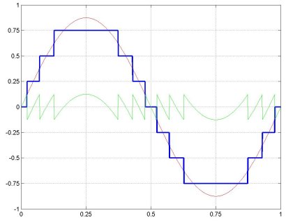
Fig. 3 Output spectrum of a CT-DSP (top) vs. a conventional (synchronous) DSP (bottom) for a 1 kHz input sinusoid where the DSP was a first-order LPF with a 3 kHz corner frequency. 8-bits of amplitude quantization, sampling in bottom plot is at 44.1 kHz.


Sampling and Quantizing1

Fig 4. Using a generic input to show how the order of sampling and quantizing may be reversed to yield the same result
(final solid black dots in each case are the same)


Fig. 4 above is a visual aid showing that the operations of quantization and sampling are interchangeable, meaning that the result of sampling then quantizing is the same as when quantizing (in CT) then sampling. The first row of Fig. 4 shows an arbitrary input that is sampled at three time instants, leading to three infinite-precision values (open circles). The next step is to round those to the nearest quantization level by passing them through a quantizer and the final result is the three solid dots.
Conversely, the bottom row shows the same input that is first passed through a quantizer, which rounds every value in the input waveform to its nearest quantization level, resulting in the thick step-wise black line. That step-wise waveform is then sampled to lead to the same three solid dots as in the top row. The conclusion is that the ordering of the two processes does not affect the final result. This idea is useful when considering how a CT DSP system has better performance than a standard (sampled) system, since the CT DSP simply quantizes the input and then operates on it, while the sampled system operates not only on the quantized signal, but the infinite unwanted aliases of the signal.


1B. Schell, Y. Tsividis "Analysis of Continuous-Time Digital Signal Processors". IEEE ISCAS May 2007, pp. 2232-2235.

Return to Bob's Home

This material is based upon work supported by the National Science Foundation under Grant No. 0209109. Any opinions, findings, and conclusions or recommendations expressed in this material are those of the author(s) and do not necessarily reflect the views of the National Science Foundation.