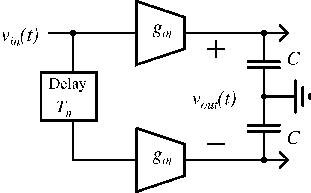
Charge-sampling techniques have recently received much attention as an alternative to voltage-sampling due to their reduced sensitivity to clock slope and jitter, and due to their fast roll-off filtering. This technique is based primarily on windowed-integration of a signal followed by sampling. The continuous-time (CT) output of an ideal windowed-integration based filter (WIBF) is vout(t) = alpha \int^t_{t - T_n} v_{in}(\tau) d\tau which means that at any given time t, the filter output is proportional to the area under the input curve v_{in}(t) over the past Tn interval (alpha is a normalizing constant). This equation can be re-written as a convolution between the input v_{in}(t) and a rectangular function rect(t/T_n - 1/2) which, thus, leads to a sinc(fTn) filtering of the input signal spectrum. This result is exploited in some recent receiver front-end designs where the null frequency, fn (= 1/Tn)) is placed at the location of the interferers in the input signal, resulting in their substantial attenuation [4]. Here, we are concerned with reducing the sampling images using the null of this sinc filter. One realization of the above equation is shown in Fig. 3(a) where an ideal broadband delay Tn defines the null frequency of WIBF and the transconductors, gm, produce currents proportional to the input signal so that the signal can be easily integrated on a capacitor C.
|
[a]
 [b]
[b]
 [c]
[c]
|
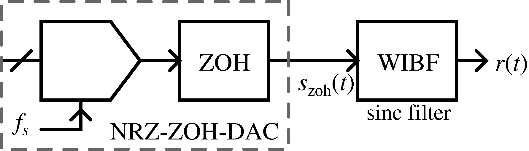
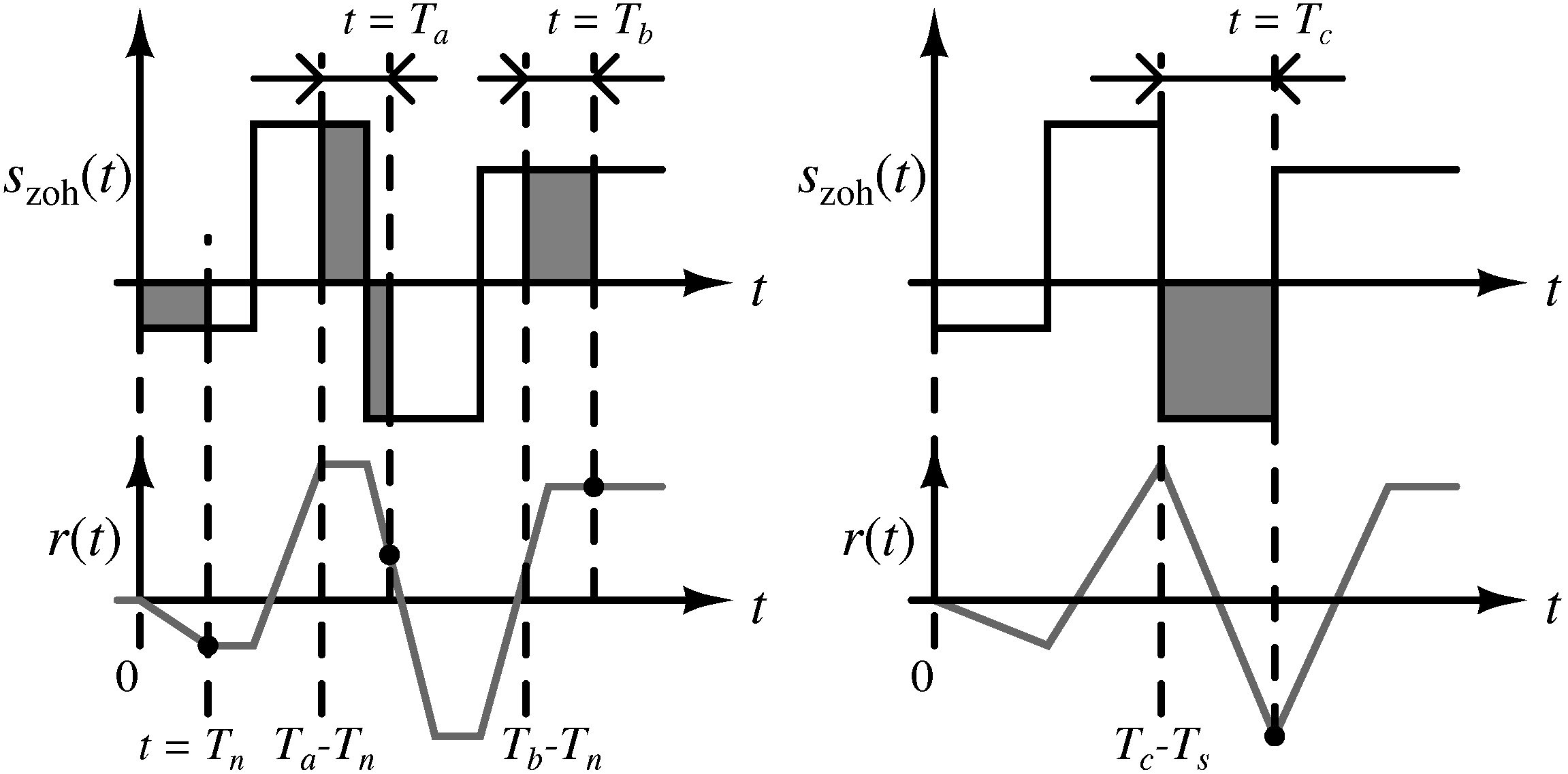
The effect of the windowed-integration when the output of a ZOH-DAC is input to the WIBF (modeled in Fig. 3(b)) is shown in Fig. 3(c).
Assume Tn < Ts and that the input to the WIBF, s_{zoh}(t), is zero before t = 0. Starting with the first sample, above equation implies that the WIBF integrates the area under the constant valued output of the ZOH-DAC as t increases from 0 to Tn (shaded portion in Fig. 3(c)), leading to a ramp signal proportional to the area, as illustrated by the bottom curve in Fig.~\ref{fig:WIBF}. The slope of this ramp is proportional to the sampled-and-held value. For Tn < t < Ts, the area under the rectangular window becomes a constant and hence the output of the WIBF is at a constant value for this interval. When the next sample arrives at t = Ts, the WIBF now sums the area under two consecutive samples falling under the window, such that the area under the old sample is decreasing while that under the new sample is increasing. The net effect is a ramp whose slope is proportional to the difference between the sampled values (see right side of Fig. 3(c)) and this process repeats for all subsequent samples.
The output of a ZOH-DAC plus WIBF system is a ramp-and-hold function between every consecutive sample values of s_{zoh}(t) [3].