
EECS 4340: Computer Hardware Design
TOOLS TUTORIAL: VHDL Design Entry and Simulation
Setup
There are a few additional set-ups that you will need in your UNIX environment to make sure you are set up in the CISL (Columbia Integrated Systems Lab) design environment.
1. If you don't already have a cds.lib file from another class, copy /tools2/courses/ee4340/public/cds.lib to cds.lib in your home directory
2. Type touch hdl.var while in your home directory. This creates a file that is needed by the VHDL simulator. Then open the file and add the line DEFINE NCELABOPTS -access rc. This passes the -access option to the nc elaborator which allows you to view the waveforms.
3. Copy the entire directory
/usr/cad/cds/tools/dfII/samples/tutorials/composer/tutorial
to your home directory:
cp -pr /usr/cad/cds/tools/dfII/samples/tutorials/composer/tutorial
Type cdsdoc at the UNIX prompt to bring up the Cadence on-line documentation. Choose the "Composer" option from the main page. Then select "Virtuoso Schematic Composer Tutorial."
Please do the Cadence Composer tutorial, Chapters 2-5. Please use the icfb& to bring up the Cadence software. It will take several hours to work through the tutorial, but it is worth it!!! It is very important that you are familiar with Composer, so please don't cut any corners here.
Creating the CellViews
In the remainder of this tutorial, you will learn how to perform VHDL simulation from the Composer interface to Cadence's NC-VHDL simulator. We will enter and simulate a simple logic design in Cadence.
First, create a library to hold your test design. To do this from the CIW choose File > New > Library. You will get a "New Library" form. In this form, enter the name "tutorial2" into the Name field. On the technology file options, choose "Don't need a techfile." Since we are only doing front-end logic design, we do not need techfile information (which contains details on a specific integrated-circuit technology). The Design Manager option should remain "No DM." The form should look like the following figure.
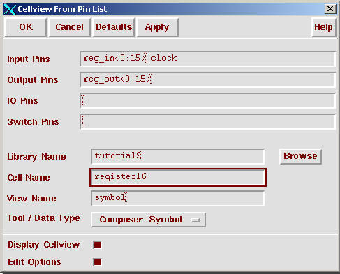
We will create a very simple binary counter using a combination of schematics and text VHDL. First create a symbol called "register16." From the symbol editor, choose Design > Create Cellview > From Pin List. In the resulting "Cellview from Pin List" form, enter the input pins reg_in<0:15> and clock and the output pin reg_out<0:15>. Choose "View Name" of "symbol" from the bottom cyclic field. Enter "register16" as the cell name. (Refer to Figure). Hit "OK." Hit "Replace" on the next box indicating that it is Okay to overwrite the symbol. You can then Okay the "Symbol Generation" form.
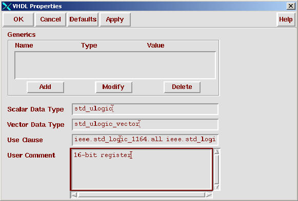
You may edit the register symbol if you want. Next choose Edit > Properties > VHDL. Under "Scalar Data Type," enter std_ulogic. Under "Vector Data Type," enter std_ulogic_vector. Under "Use Clause," enter ieee.std_logic_1164.all and ieee.std_logic_arith.all. Under "User Comment," you can add "16-bit register" (Refer to Figure).
You can now create the VHDL entity from the symbol. Choose Design > Create CellView > From Cellview. Make sure that the "From View Name" is set to symbol and that the "To View Name" is set to VHDL. Hit "OK." The entity that is automatically created now appears in Emacs for you to edit if necessary (actually, this should not be necessary). Emacs is running some special templates to help the VHDL novice. For more details in this VHDL language-sensitive editor, please see the on-line documentation in cdsdoc.
Now we need to create the architecture for this 16-bit register. Create a CellView from the CIW. Type in for the "View Name" field "behavior." Any name can be used but we will use "behavior" as the name for the VHDL architecture. On the "Create New File" form, specify "VHDL-Editor" as the "tool" field. and verify that the "Cell Name" is the cell you are currently making an architecture for. "OK" the form, which brings up Emacs again (Refer to Figure).
We now need to enter the VHDL architecture for this component:
architecture behavior of register16
is
begin
SYNCH: process(clock)
begin
if (clock = '1' and not (clock'stable))
then
reg_out(0 to
15) <= reg_in(0 to 15);
end if;
end process;
end behavior;
Save the design and exit Emacs.
Now, let's create a multiplexer, cell name "multiplexer" with pins in0<0:15>, in1<0:15>, and select_in and output mux_out<0:15>. Create the symbol and the entity as before. Don't forget to add the correct VHDL properties on the symbol. Next, create an architecture in the "behavior" view for this component:
architecture behavior of
multiplexer is
begin
process(select_in, in0, in1)
begin
if(select_in = '0') then
mux_out <= in0;
elsif (select_in = '1') then
mux_out <= in1;
else
mux_out <= "XXXXXXXXXXXXXXXX";
end if;
end process;
end behavior;
The final component we need before assembling the top-level
schematic is an incrementer, cell name "incrementer" with pins
incr_in<0:15> and
output incr_out<0:15>. Create the symbol and entity as before. The
"behavior" view for this component is as follows:
architecture behavior of
incrementer is
begin
incr_out <= to_stdulogicvector(unsigned(incr_in) + '1');
end behavior;
Finally, we need to make the top-level schematic, cell name "top_level." Instantiate a "multiplexer", a "register16" and an "incrementer." There are three inputs of the top-level schematic, clock, start<0:15> and load_start. Wire up the schematic so that the multiplexer feeds the register, which feeds the incrementer (Refer to Figure). The output of the incrementer then feeds back around to go into the in0 input of the multipexer. the in1 input of the multiplexer gets the input from start and the select of the multiplexer gets the input from load_start. Check and save your schematic when you have finished the wiring. Choose Edit > Properties > VHDL and add the VHDL properties in a manner similar to how it was done for the symbols, then make the VHDL top_level entity.
Debugging
We now need to set up the VHDL environment, netlist, and simulate the design. From the CIW, choose Tools > VHDL Tool Box. The Toolbox should be NC-VHDL as you will see when you run the later steps.
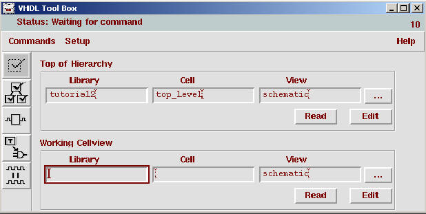
We will now create a simple testbench to test this design. Enter the library and cell name ("tutorial2" and "top_level") in the "Top of Hierarchy" field. Choose Commands > Create Test Bench. Leave the "Stimulus File Name" field blank and "OK" the form. The cell name "test" with the architecture "stimulus" is created and displayed in the Emacs as a template for your testbench. First modify the signal declarations to include initial conditions:
SIGNAL clock : std_ulogic := '0';
SIGNAL load_start : std_ulogic := '1';
SIGNAL start : std_ulogic_vector(0 TO 15) := "0000000000000000";
We will enter a very simple testbench into the architecture body after the "dut" instantiation:
clock <= not(clock) after 10 ns;
load_start <= '0' after 15 ns;
You may also need to add the component binding:
FOR ALL: top_level USE ENTITY
tutorial2.top_level(schematic);
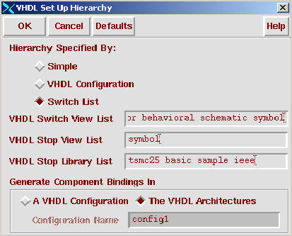
Now, we need to set up the netlisting. From the VHDL Toolbox, choose Setup > Hierarchy. Select Switch List and select "The VHDL Architectures" button for the location of the component bindings. "OK" the form. (Refer to Figure)
Now choose Commands > Check Hierarchy to netlist and syntax check your design, creating a simulatable VHDL model for NC-VHDL. If there are any errors, they are reported and Emacs is automatically brought up with the errors highlighted. Correct any syntax errors and repeat Commands > Check Hierarchy until the design cleanly analyzes and elaborates.
Now, we are going to simulate the design. Choose Commands > Simulate. The NC-VHDL simulator window appears.
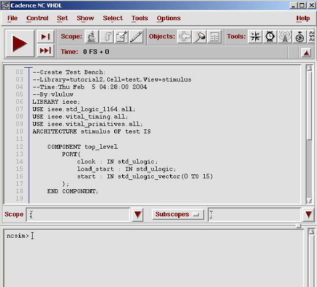
Choose Windows > Navigator, opening a "Navigator" window. Clicking on the top level icon displays the hierarchy under the top level. There should be three components listed: dut, $PROCESS_000, and $PROCESS_001. Select $PROCESS_000 in the Navigator Window. Highlight $PROCESS_000 and with the right mouse button select Set Debug Scope. In the source window, you'll see the source displayed for testbench and the line below highlighted:
clock <= not(clock) after 10 ns;
The designation $PROCESS_000 corresponds to this line of concurrent VHDL (you can think of each state of concurrent VHDL as representing a process). Double-clicking on dut causes the hierarchy under this level to expand.
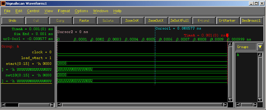
Now we are going to set up for a waveform trace and run the simulator. From the "Navigator" window, select dut and with the right mouse button select Wave Trace. This should add all the signals at the top level of the design into the waveform tool (SimVision), which should automatically come up. Now let's run the simulator for 1000 ns. From the VHDL simulation window, choose Set > Breakpoint > Time. Enter 1000 ns in the Time window. Leapfrog should run for 1000 ns and then stop with the waveform recorded into the open SimVision window.
Once you are here, play around with the Debugger, make the Debugger your friend!!!